Filters for AC power
Introduction
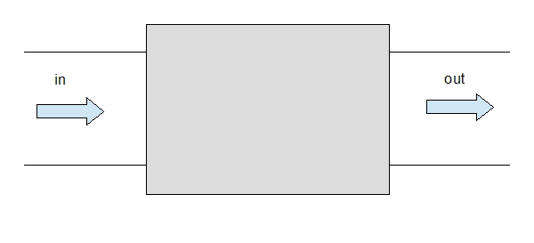
Filters are devices that can absorb part of an electromagnetic wave that is travelling along a cable. Sometimes the EMF is carried along an AC power cable, and then it is radiated into space by other devices, or at the terminations of the cable. In these cases some AC filters may be effective
 |
 |
Attenuation
The attenuation of a filter is the ratio of the amplitude of an electric wave that enters the filter divided by the amplitude of the output wave. Since the filter is supposed to reduce the amplitude of the wave this ratio is greater than one. Commonly this ratio is expressed in dB, decibel, which is defined as follows:
Adb = 20 log10 ( Vin / Vout )
The reason for using the decibel for measuring the attenuation of filters is that when multiple filters are connected in cascade the total attenuation of the cascade of filters in dB is the sum of the attenuations of the single filters in dB.
The dB is based on the logarithm so a change of 1 dB is not the same at every level, but it is proportional to the power of ten of the interval. The following table summarizes the actual ratio of amplitudes that correspond to some values of attenuation given in dB
| 0 dB | 1 | no attenuation | 100 |
| 20 dB | 0.1 | 1/10 | 10-1 |
| 40 dB | 0.01 | 1/100 | 10-2 |
| 60 dB | 0.001 | 1/1000 | 10-3 |
| 80 dB | 0.0001 | 1/10000 | 10-4 |
| 100 dB | 0.00001 | 1/100000 | 10-5 |
Theory
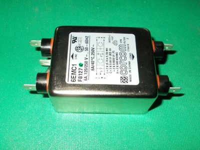
Almost all commercial AC filters are made of discrete components, like capacitors, inductors, coupled inductors, and are enclosed in a metal box that protects the components and also prevents the electromagnetic waves from escaping, or entering the enclosure. The only passage of the electromagnetic wave in and out of the filter is through the connectors.
These filters are designed using the theory of electric circuits composed of lumped elements. A lumped element is a structure of limited size, that has electrical properties very different from a plain conducting wire, and so has some effects on an electromagnetic wave that travels along the wire.
Typical lumped elements are the resistors, capacitors and inductors. Most filters use also coupled inductors.
All these filters are completely passive, which means that the only electromagnetic energy that goes into the filter is the energy of the electromagnetic wave to be filtered.
The filter is supposed to cancel, or at least reduce the amplitude, of the electromagnetic waves, so it means that the electromagnetic power that exits from the filter is smaller than the electromagnetic power that enters into the filter, and since energy or power is never destroyed but only transformed, the missing power is turned into heat inside the filter. Usually the actual power associated to the electromagnetic noise is too small to really heat up the filter.
Filters may also deviate the electromagnetic wave toward the ground, if the ground contact is effective.
Most filters have one stage of circuit, which contains a coupled inductor, and bypass capacitors. For higher attenuations we have to use two-stage filters and possibly three-stage filters, which of course are also bigger and more expensive.
Connection in cascade
Usually it is possible to insert multiple filters on the same line one after the other. This is called a cascade of filters. The filtering effects are combined, the total attenuation of the cascade is the product of the attenuations of the single filters, so the total attenuation expressed in dB is the sum of the attenuations of the single filters expressed in dB.
A cascade of filters can be useful to have a higher attenuation for a given frequency band, or to have some attenuation in a wider frequency band.
For example if two identical filters are cascaded, the attenuation will be doubled in the frequency band of these filters, but it will be still negligible in the frequency band where these filters have negligible attenuation. Otherwise if the first filter works well in a frequency band, and the other in another frequency band, the cascade will have a good attenuation in both frequency bands.
Common mode and differential mode
This section will be available soon.
Using AC filters for DC
It is also possible to use AC power filters for a low voltage DC circuit. The DC voltage passes through the filter unchanged. Notice that a DC voltage has a polarity, usually the connectors of the input side correspond directly and clearly to the connectors of the output side so the polarity can be respected.
Connection
Most filters have the 6.3 mm Faston connectors. It is also possible to solder the wires directly on the plates of the connectors but it is better to use the corresponding female connectors to connect the wires, so the wires can also be detached if needed, and the filter can be reused easily.
Product choices
There are hundreds of products on the market for AC filters. They differ in the maximum current that they can sustain, in size and shape, and most importantly their characteristic of attenuation versus frequency.
Ideally the filter should be matched to the frequency band of the electromagnetic noise that we want to suppress.
For example if the electromagnetic noise in a cable has frequency between 1 MHz and 10 MHz, then the best filter for this case is one that has the highest attenuation right in this interval of frequency.
But often the frequency band of the EM noise to suppress is not well know in advance.
Since the AC power works at 50 Hz or 60 Hz according to the country, an ideal AC filter should have a very high attenuation at every frequency above these, for example from 100 Hz upwards.
But real filters available on the market, or that can be built with a number of components, do not have this characteristic.
So the choice of the filter has to be done by an approximation and guess, and at the end the effectiveness of the filter can be verified only once the filter has been installed.
Related pages
Filters examples
Filters applied to ADSL systems
Filters database